

How To Draw A Deck Of A Ship
When a new ship is designed, i of the primary steps involved in the development of the concept, is designing its General Arrangement and allocating proper spaces according to the requirements of the possessor and functionality of the ship. It is up to the naval architect to decide on the ship'south general arrangement, depending on many blueprint constraints that are mentioned in the technical specifications of the contract.
So how exactly do you decide on a ship'southward full general arrangement, and design the most optimum one for that particular projection?
Since virtually all ships have something unique in their general organisation, there is no specific procedure with rules stated for the same. But in spite of that, a naval architect needs to know the basic procedure to follow in order to come down to an optimum design. In this article, we shall discuss a general procedure that is followed in the transport designing industry.
Initially, in lodge to have a visual approximation of the ship dimensions, draw an outline of the contour view, chief deck or uppermost deck that contributes to longitudinal strength, and the forecastle deck. In some ships, the upper deck is stepped, i.eastward. it has a poop deck at the aft. Make certain you show that in the profile view and the deck outline view.
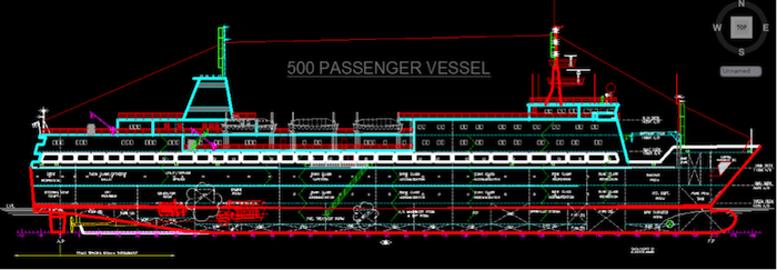
Figure one: Contour view of a 500 Pax transport
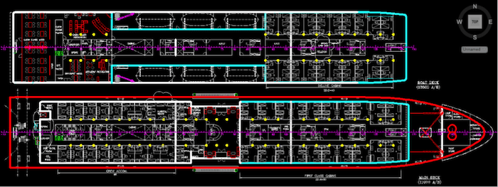
Figure 2: Main deck and Boat deck plan
The reasons behind deciding the particulars (Especially superlative) of the forecastle deck at this stage are as follows:
- Minimum bow height has to be attained (co-ordinate to ILLC Regulations) in club to reduce the deck wetness
- To provide forecastle deck area for anchoring and mooring equipment
- Adequate volume underneath for storage and concatenation locker, etc.
- To provide additional cargo space (in lower decks) in case of certain ships
After having fatigued the profile programme, the first thing a designer should do is decide on the framing and frame spacing of the send. The framing, whether longitudinal or transverse is decided on the basis of the length of the vessel. More often than not, all ships longer than 120 1000 are longitudinally strengthened.
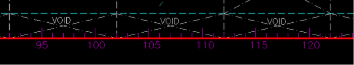
Figure three: Discover how the frame spacing is shown in the cartoon
The frame spacing is then calculated by the formula specified in the rule volume of the authorised classification guild. The value obtained from the formula is generally rounded off to the nearest hundreds or fifties, and so as to reach ease of production and design.
Next is to marking the decided frame spacing of the drawing. This frame spacing will now deed equally scale on the drawing, helping you to locate every point on the ship.
Y'all must now separate the transport into certain number of watertight compartments, which is decided past the subdivision rules prescribed by the classification society. The rules specify the total number of watertight transverse bulkheads that are necessary to maintain watertight integrity of the ship. A send generally has 4 types of transverse bulkheads:
- A fore pinnacle standoff bulkhead
- An aft-summit bulkhead
- A bulkhead at each terminate of mechanism space
- Transverse bulkheads in cargo hold regions
Once the number of bulkheads accept been decided, the length and number of holds should be planned accordingly. The ordinary transverse watertight bulkheads in the holds should be spaced at reasonably uniform intervals. Where non-uniform spacing is unavoidable and the length of a agree is unusually large, the transverse forcefulness of the send is to be maintained past providing additional spider web frames, increased framing etc.
In some cases, the decided number of bulkheads may interfere with the functionality of the send or the specific requirements of that particular type of trade. Proposals to dispense with ane or more transverse bulkheads in such cases can be considered by the classification club, provided it does affect the watertight integrity of the send.
How to decide the position of the fore peak collision bulkhead?
- The distance of the forepeak standoff bulkhead from the forwards perpendicular is decided based on formulae prescribed by the authorised classification society. Mostly, the class lodge would provide you with two formulae. 1, to specify the minimum distance of the forepeak bulkhead aft of the forward perpendicular. Other, to specify the maximum distance of the forepeak bulkhead aft of the forward perpendicular
- It is up to yous, every bit a designer, to provide the forepeak standoff bulkheads within the above limits, depending on the dimensions of the forepeak ballast tank, anchor equipment, and chain locker dimensions
How to decide the position of the fore superlative standoff bulkhead?
The following considerations are taken during deciding the position of the aft peak bulkhead or the engine room aft bulkhead. First, the position of the engine room forward bulkhead is stock-still according the position and length of the holds. Once that is done, nearly iv frame spaces need to be left out before placing the main engine aft of the engine room forrad bulkhead. That is to exit space for maintenance and crew operations.
Aft of the empty space, the length of the engine room is to be decided depending upon the length of the principal engine, and the length of the intermediate shaft. Now, the intermediate shaft is coupled with the propeller shaft past a flanged connection. The coupling flange between the intermediate shaft and the propeller shaft is to be housed within the engine room itself. It is just aft of the coupling flange that the engine room aft bulkhead is positioned.
The propeller shaft runs from aft of the engine room bulkhead connecting to the propeller through the stern tube.
In many cases, the position of the engine rom aft bulkhead is likewise governed past the decided capacity of the aft peak ballast tank, which is always aft of the aft acme bulkhead. The chapters of the tank is estimated past trim and stability calculations, which is a very preliminary stage of design. But the engine and shaft lengths are decided at a insufficiently afterwards stage. This should give you lot an thought of how iterative the transport design process is.
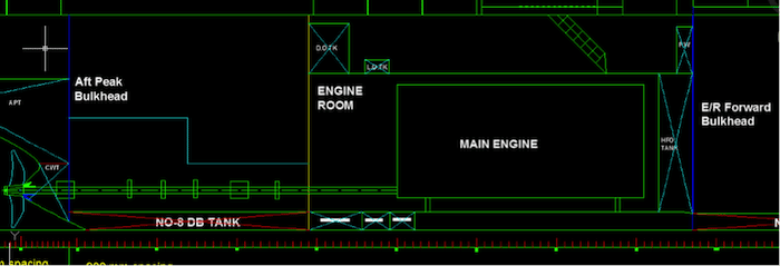
Effigy iv: Aft elevation bulkhead position
How to accommodate the cargo spaces?
The entire cargo space needs to exist divided into cargo holds by placing the specified number of transverse watertight bulkheads. The longitudinal position of the bulkheads may be decided according to a few principles of cargo requirement:
- Holds should be kept of equal lengths wherever possible
- In some cases where necessary, alternating large and small holds are designed to meet the cargo requirements for unlike voyage and cargo conditions. This is ordinarily done for bulk carriers, product tankers, and container ships
- Sometimes, a single large cargo concur (for large multipurpose carriers)
In cases of oil tankers and container ships, decisions on longitudinal bulkheads are to be taken, with respect to prevention of costless surface outcome, ensure proper cargo distribution and handling characteristics.
In case of majority carriers, the slope of the tank top sloping bulkhead is to exist taken care of. The tank gradient must be more than the angle of repose of the cargo, which is mostly around 30 degrees. The slope of the bottom tank is by and large maintained at 45 degrees.
In a general arrangement, the double bottom acme needs to be shown conspicuously, so as to ensure proper estimation and representation of the tank programme. Therefore the designer is required to estimate the height of the double bottom using the corresponding formula specified in the rules of the authorised class guild.
Decide on the height of the tween decks. Ships that carry packed cargo and cars, require more deck space to reach maximum stowage capacity. In guild to increase the overall deck area, these ships are provided with a number of tween decks. The height of each tween deck should exist sufficient to arrange the cargo that is to exist stowed on it.
This consideration of tween deck is even so not required for volume based cargo carrier, similar oil tankers, chemic carriers and bulk carriers. And in case of container ships, the height of each container serves every bit the flooring for the adjacent container to be stowed above it, hence container ships practise not require tween decks for cargo stowage.
Afterwards having decided on the capacities and sizes of the cargo holds, the size of hatch openings and hatch covers.
Anchor Tank Capacities and Tank Plan Design
Anchor water is required for empty voyage to have proper sinkage, trim and stability.
Excessive ballast chapters is bad since it is expensive and takes up useful space. Ballast chapters should be such that full propeller immersion is obtained at the aft cease and forrad draught is not as well depression to avoid the harmful effects of slamming.
Approximately in a ballast voyage, displacement is 0.5 of fully loaded displacement which is about 0.55 of full draught. Ballast distribution should be such that excessive hogging moment is avoided in this condition. So a designer should always ensure to segregate the ballast h2o tank from any other liquid tank.
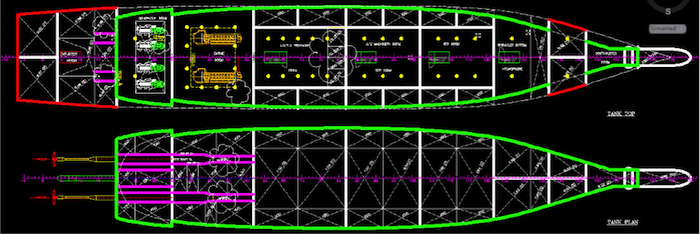
Effigy 5: Tank top plan and Tank plan
At that place are a few other points that a designer must consider while making tank arrangements for ships:
- No access is required except for cleaning and maintenance. Minimum two manholes are to be provided on top, and preferably at the diagonal corners of the tanks so that they are maximum distance from each other
- Tanks and pipes carrying a particular type of liquid must be segregated from those carrying some other type of liquid. They should also be colour coded differently
- Fresh h2o tank should not have any tank side by side to itself. So a fresh h2o tank and whatsoever other tank must be separated by a cofferdam. For the same reason, FW tanks cannot be placed below the load waterline
- Since total liquid carried is relatively low, the tanks may conveniently be situated in the lower portions to increase transverse stability of the send
- To simplify piping arrangements, and the total length of piping, fresh water tanks should be near the engine room, every bit well as accommodation. Dirty oil and heavy fuel oil tanks should be near the engine room. Dirty oil and sludge tanks can be conveniently located in the double bottom of the engine room
- W. tanks should be well distributed all over the length and latitude of ship to help the ship attain its stability and trim requirements. Pipes should not run within tanks carrying another liquid, i.e. fuel oil piping should non run through whatsoever ballast water tank
- Consumable tanks (Heavy Fuel Oil, Dirty Oil, and Fresh Water) should be so located that their consumption does not cause unnecessary adverse trim. They should non cause unduly agin free surface effects. So these tanks should be divided into smaller tanks with reduced jiff. Too many small tanks, however, will make complicated piping system
- W. tanks are either fully pressed or empty ballast h2o tanks should be distributed all over the length of send with sufficient capacity in the peak tanks to adapt for the required trim and stability
- Tanks should exist distributed symmetrically about centreline of the ship, so that adverse heel effects are not felt. If there is whatsoever such upshot (harm stability) cross-connection between port and starboard tanks may be provided
- The boundaries of double bottom tanks, deep tanks etc. should be designed to withstand the applied hydrostatic pressure
- The tank distribution should not adversely bear on the longitudinal forcefulness of hull girder
Lastly, it is important to sympathise and know, that a general organisation of any send will consist of the drawings of the following views:
- Contour View (generally looking from starboard side)
- Midship sections (looking from aft, and looking from forrard)
- Main deck plan (also shows the accommodation layout)
- Navigation deck plan.
- Forecastle deck plan
- Tank top programme
- Tank plan
Information technology should too be noted that a the process of developing the general arrangement drawing is slightly dissimilar for various pattern firms, depending on their procedures and practices, all the same the underlying principle always remains the same. It is an iterative process, and the final GA is a arrived at, after repeated approvals by the nomenclature guild and the owners political party.

Source: https://www.marineinsight.com/naval-architecture/procedure-for-designing-a-ships-general-arrangement/
Posted by: holleyseentrusels.blogspot.com
0 Response to "How To Draw A Deck Of A Ship"
Post a Comment